|
MCC Block Casting ID Code
This is the block casting ID code for a '77-up MCC truck
block (D7TE-A-2-B).
Notice the code appears upside down, about an inch and a
half below the deck,
on the right side of the engine, toward the rear. If this
engine was installed
in a vehicle, you wouldn't be able to see the block casting
ID code without
removing the starter.
All blocks designed for trucks have the D7TE prefix. Truck
blocks have a
revised #3 main (thrust) bearing support web to withstand
the additional
thrust load imposed by a clutch.
|

|
|
Build Date Stamp
The original build date of the engine is stamped into the
front cover surface,
toward the right side of the engine. Often this stamp is
behind the front cover
gasket so it is not visible with the front cover plate on
the engine. In this
case, it was outside of the front cover gasket.
The build date was the date on which the engine was
assembled at the factory.
The build date code in this picture is: “78G190” This
translates to July 19,
1978.
|

|
|
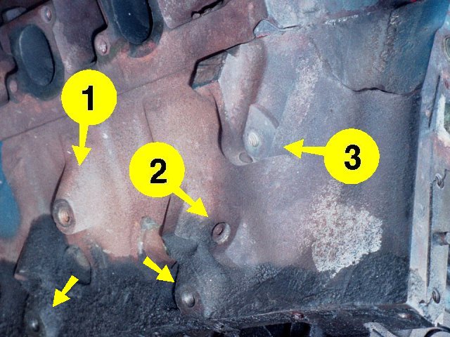
Block Features (right side)
-
Upper engine mount boss. Engine mounts attach to the
upper boss and two lower
bosses just above the oil pan flange at the bottom of the
block (arrows).
-
Threaded plug into the water jacket.
-
Lower accessory bracket mounting flange on right front of
block.
Just above the "3" is the oil dipstick hole used for
front-sump applications
(i.e., cars and pre-1980 4x2 trucks).
|

|
|
Block Features (left side)
-
Upper engine mount boss.
-
Threaded plug into the water jacket. This plug
corresponds to the one on
the right front of the block (previous picture).
Threaded plugs in the lower water jacket might have been
intended to support
an alternative cooling system, such as in a marine or
industrial
application.
|

|
|
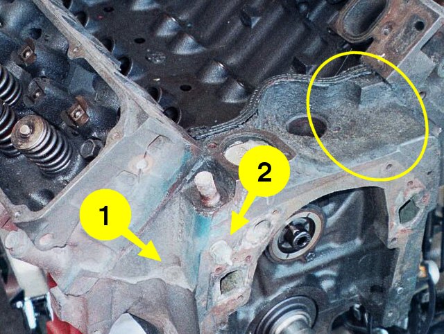
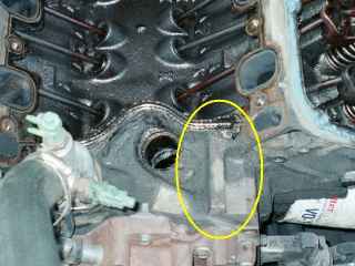
Block Features (front)
-
Plugged dipstick hole used for cars and pre-1980 4x2
trucks with front-sump
oil pans. All '80-up trucks require a rear-sump oil pan
to clear a
crossmember, so all '80-'82 M-blocks use the left side,
oil pan dipstick
mounting.
-
Coolant temperature sending unit.
Note the circled area with no raised web beside the
distributor hole.
|

|
|
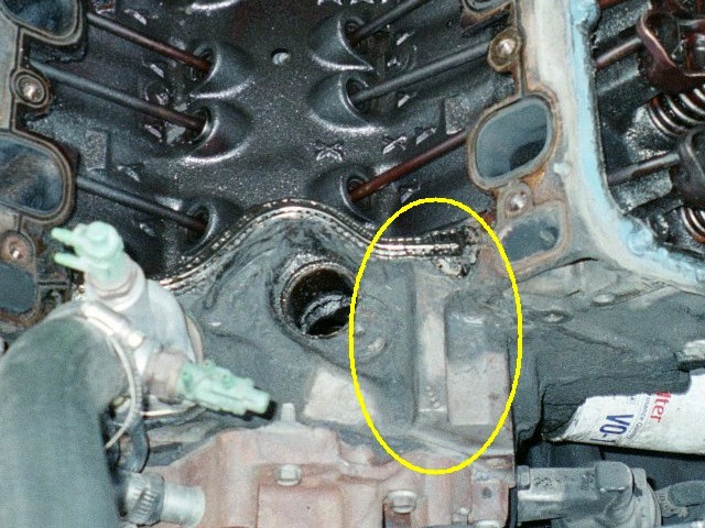
No Web on Block Front
Many M-block (351M/400) engine blocks have a 5/8" tall
raised web just
left of the distributor hole, on the top of the block.
However, not all
M-blocks have that web, as this photo (and the previous
photo) of a 1978
MCC block shows.
Some people say you can distinguish an M-block from a 351
Cleveland block
by that web. It's true that no 351 Cleveland blocks have
that web, but not
all M-blocks do either. While presence of the web rules out a
351 Cleveland,
absence of the web does not rule out an M-block.
|

|
|
Web on Block Front
This photo of a 1979 CF block shows the raised web to the
left of the
distributor hole on the front of the block. The raised web
is an
extension of the engine block’s front intake manifold gasket
surface.
|
|
|
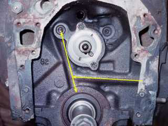
Oil System
This picture of the front of the block shows the oil gallery
casting
bosses. All oil galleries in the block are drilled through
the raw
casting.
Arrows show the path of oil when it leaves the filter. Oil
flows from the
filter adapter on the left side of the block, into the
crossover gallery
that runs above the crankshaft, over to the right side of
the engine.
From there, oil feeds the #1 main crankshaft bearing below,
and the main
distribution gallery (right side lifter gallery) above.
|

|
|
Crossover Oil Gallery Port
This picture shows the left front side of the block. Toward
the front, on
the side of the front cover housing, is the fuel pump
mounting hole. Beside
that (arrow) is the outer end of the oil gallery fed
directly from the
filter. To the right is the oil filter adapter. The center
passage in the
oil filter adapter is drilled into the crossover oil
gallery.
The end of the crossover oil gallery is usually plugged on
the side of the
block. This is where you can tap into pressurized oil for an
external oil
line to help feed the rear mains.
|

|
|
Oil Pressure Sending Unit
This picture shows the oil pressure sending unit on the top
rear of the
block. The arrow indicates the oil gallery that feeds the
sending unit from
the rear end of the main distribution gallery (right side
lifter gallery).
An external oil line can feed pressurized oil into this
port, providing
higher oil pressure for the last two main crankshaft
bearings.
Using an external oil line will improve the longevity of the
main crankshaft
bearings, even on a stock-level rebuild.
|

|
|
Crankshaft Casting Marks
-
Cleveland Foundry (CF) mark on #1 main bearing cap. Main
bearing caps #1
through #4 are marked with the position number, an arrow
pointing toward
the front of the engine, a foundry mark, and sometimes a
date code. The
date code on this cap is 8F12 (June 12, 1978).
-
Crankshaft ID code (1KA) for a 351M crankshaft. The 351M
ID code is cast
into the side of the first counterweight. Just below the
casting ID code
in the picture is a letter "H" stamped into a machined
surface. That is
probably a quality control mark.
|

|
|
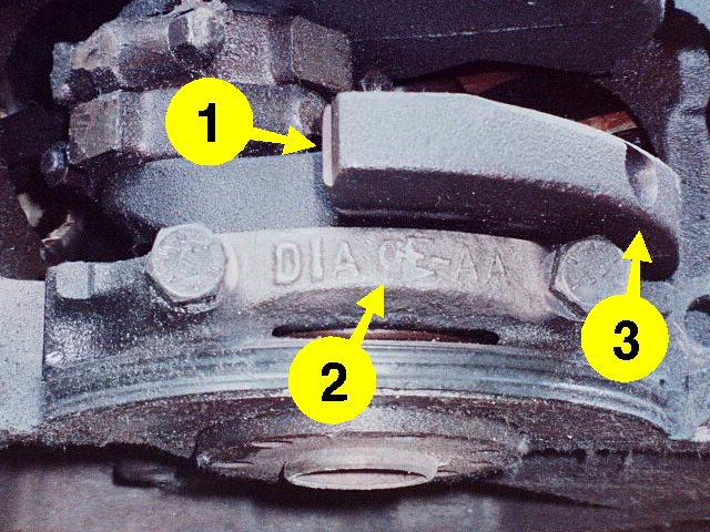
More Crankshaft Casting Marks
-
(and 3.) Machined and drilled parts of the rear
crankshaft counterweight.
These are adjustments to balance the crankshaft at the
factory.
-
Cleveland Foundry (CF) mark on #5 main bearing cap. The
#5 main bearing cap
is usually not marked because it is unique, wider than
the other main
bearing caps, with a groove for the rear main seal. Note
that the main
bearing cap in this D7TE engine is the original 400
design from 1971
(D1AE-AA).
|

|
|
Connecting Rod Casting Marks
The casting ID codes are clearly visible on this rod end
cap. Once again, note
that the connecting rods in this D7TE engine are the
original 400 design from
1971 (D1AE-AA). Many M-block components did not change
significantly from the
original 400 design.
The machined surface in the middle of the connecting rod end
is evidence of
factory balancing.
Sometimes, you can find a casting date code on the other
side of the connecting
rod end from the casting ID codes.
|

|
|
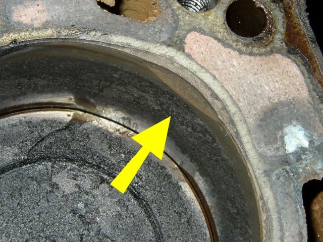
Cylinder Wall Valve Relief
M-block and 351 Cleveland cylinder walls have a valve relief
notch cut into
the upper edge to allow clearance for the intake valve’s
head.
Even the smaller M-block and 351C 2V intake valves (2.041"
head diameter) are
rather large compared to other engines with similar
displacement.
|

|