|
MCC Cylinder Head Casting Marks
This picture shows typical casting marks on a '75-up M-block
cylinder
head from the Michigan Casting Center (MCC).
-
Casting date code. "G11" indicates July 11th. Notice the
year digit
is missing.
-
Foundry mark. All later M-block cylinder heads were cast
at either
the Michigan Casting Center (MCC) or the Cleveland Foundry
(CF).
-
No mark on the upper corner of the head. Some M-block
heads have a
raised "M" in that location.
|

|
|
More Cylinder Head Casting Marks
-
Casting ID code. "D5AE A-2-A" identifies the specific
casting design.
All M-block cylinder heads manufactured after the 1974
model year
(including all 351Ms and all truck engines) use the D5AE
casting ID
prefix.
-
No mark on the upper corner of the head. All 351C cylinder
heads have
either "2" or "4" in that location to identify 2V heads
and 4V heads.
Only (some) M-block heads were made with no mark in that
location.
|

|
|
Valve Springs and Retainers
Starting in MY1978 through the end of M-block production in
the 1982 model
year, Ford used different valve springs and retainers on
M-block intake and
exhaust valves. Before that period, M-block intake and
exhaust valves used
the same springs and retainers.
This picture shows the difference between the intake valve
spring retainer
(right circled) and the exhaust valve spring retainer (left
circled).
These '78-up exhaust valve springs have 0.13" shorter free
height and
solid height, and 0.14" shorter installed height than the
intake valves.
|

|
|
Exhaust Ports
Notice the accumulation of soot in the bottom of the exhaust
ports.
This is really a dramatic illustration of the flow path in
the
exhaust port.
Exhaust gas tends to follow the upper surface of the exhaust
port,
and the hot exhaust gas flowing continuously across those
surfaces
keeps them clean and free of deposits. In contrast, exhaust
swirls
around in the lower part of the port, cooling and lingering
long
enough to deposit soot and other residues on the lower port
surfaces.
This problem is more pronounced in 351C 4V exhaust ports.
|

|
|
Combustion Chamber
This is the standard large M-block combustion chamber
(78cc),
with the standard 2V valves (intake 2.04" diameter, exhaust
1.65"
diameter). Because of the depth of these chambers, the first
0.02" to 0.03" milled from the deck face reduces unswept
volume by the height of a cylinder.
The angle of the spark plug hole, and obstructions above the
hole on the outside of the cylinder head, preclude inserting
a rod
(even as thin as a coat hanger) in line with the bore axis
for
an accurate stroke measurement.
|

|
|
Thermactor AIR Passages
On M-block engines equipped with the Thermactor AIR (air
injection
reaction) system, fresh air is injected directly into the
exhaust ports
in the cylinder heads. Fresh air is routed to the exhaust
ports through
AIR system passages in the cylinder head. These passages are
drilled
through the cast iron head.
The main distribution passage is drilled all the way through
the
cylinder head, from one end to the other, just above the
exhaust ports.
The arrow in this picture identifies one end of that main
passage.
|

|
|
More Thermactor AIR Passages
The pictures on the right illustrate the locations of the
drilled
AIR system passages in the cylinder head.
Top: From the top of the cylinder head, bosses are
visible for the AIR
system passages drilled across the head, from the intake
manifold
mating surface to the main distribution passage.
Bottom: The yellow lines show where the AIR system
passages are drilled.
|


|
|
AIR Bump in Exhaust Port
Beginning in MY1973, an AIR “bump” was added to the top
of the exhaust port in M-block cylinder heads. The AIR bump
was connected to the AIR system main distribution passage
above the
exhaust port by a hole drilled through the bump.
This picture shows AIR bumps in two adjacent ports. The bump
in port #1 is not drilled, while the bump in port #2 is.
One exhaust port feeds the exhaust crossover (second from
the right
when facing the ports), and the AIR bump was not drilled in
that
port.
|

|
|
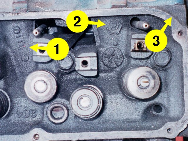
Thermactor AIR and
Exhaust Crossover
-
Thermactor AIR passages at each end of the cylinder head.
These passages
are drilled from the intake side across to the main
distribution passage
above the exhaust ports.
-
Exhaust crossover passage. This passage feeds exhaust gas
from an
exhaust port to the crossover in the intake manifold.
The exhaust port connected to the crossover passage is not
connected
to the AIR system.
|

|
|
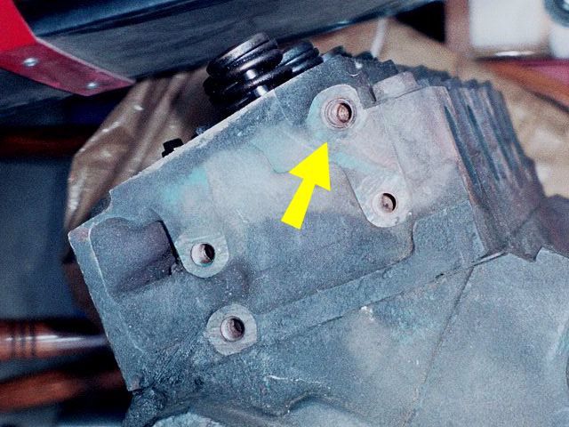
Exhaust Crossover Cooling
Just above the exhaust crossover port on the cylinder head
intake
face is a blind hole (arrow). It is partially exposed above
the
edge of the intake manifold when the manifold is installed.
The purpose of this hole is to relieve heat from the
cylinder
head’s exhaust crossover passage. Some people are tempted to
plug
it or fill it, perhaps to keep debris from accumulating in
it.
However, that would
defeat the purpose of the hole, and it would aggravate the
heat
problems inherent in the exhuast crossover design.
|

|